|
高士涛-学习日报 |
|||||||
|
姓名 |
高士涛 |
日期 |
2023/06/29 |
部门 |
云服务业务部 |
导师 |
王晓明 |
|
学习工作内容 |
|||||||
|
M-LAG学习文档 |
|||||||
|
M-LAG参考文档 什么是M-LAG?为什么需要M-LAG? - 华为 (huawei.com) 1.23
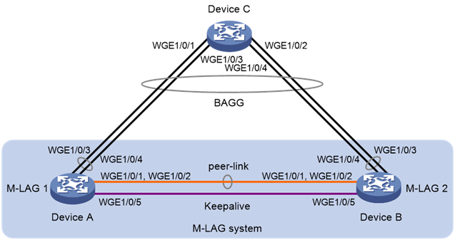
M-LAG典型配置举例 1.23.1 M-LAG基本功能配置举例 1. 组网需求 ・ 由于用户对于业务的可靠性要求很高,如果Device C和接入设备(Device A和Device B)之间配置链路聚合只能保证链路级的可靠性,接入设备发生故障时则会导致业务中断。这时用户可以采用M-LAG技术,正常工作时链路进行负载分担且任何一台设备故障对业务均没有影响,保证业务的高可靠性。 ・ 配置三层以太网接口为保留接口,在该三层以太网接口上搭建Keepalive链路,保证Keepalive报文能够正常传输。 2. 组网图 图1-14 M-LAG基本功能配置组网图
3. 配置步骤 (1) 配置Device A # 系统配置。 <DeviceA> system-view [DeviceA] m-lag system-mac 1-1-1 [DeviceA] m-lag system-number 1 [DeviceA] m-lag system-priority 123 # 配置Keepalive报文的目的IP地址和源IP地址。 [DeviceA] m-lag keepalive ip
destination 1.1.1.1 source 1.1.1.2 # 配置端口Twenty-FiveGigE1/0/5工作在三层模式,并配置IP地址为Keepalive报文的源IP地址。 [DeviceA] interface twenty-fivegige
1/0/5 [DeviceA-Twenty-FiveGigE1/0/5] port link-mode route [DeviceA-Twenty-FiveGigE1/0/5] ip address
1.1.1.2 24 [DeviceA-Twenty-FiveGigE1/0/5] quit # 配置Keepalive链路接口为保留接口。 [DeviceA] m-lag mad exclude interface twenty-fivegige 1/0/5 # 创建二层聚合接口3,并配置该接口为动态聚合模式。 [DeviceA] interface bridge-aggregation 3 [DeviceA-Bridge-Aggregation3] link-aggregation mode dynamic [DeviceA-Bridge-Aggregation3] quit # 分别将端口Twenty-FiveGigE1/0/1和Twenty-FiveGigE1/0/2加入到聚合组3中。 [DeviceA] interface twenty-fivegige
1/0/1 [DeviceA-Twenty-FiveGigE1/0/1] port link-aggregation group 3 [DeviceA-Twenty-FiveGigE1/0/1] quit [DeviceA] interface twenty-fivegige
1/0/2 [DeviceA-Twenty-FiveGigE1/0/2] port link-aggregation group 3 [DeviceA-Twenty-FiveGigE1/0/2] quit # 将二层聚合接口3配置为peer-link接口。 [DeviceA] interface bridge-aggregation 3 [DeviceA-Bridge-Aggregation3] port m-lag peer-link 1 [DeviceA-Bridge-Aggregation3] undo mac-address static source-check enable [DeviceA-Bridge-Aggregation3] quit # 创建二层聚合接口4,并配置该接口为动态聚合模式。 [DeviceA] interface bridge-aggregation 4 [DeviceA-Bridge-Aggregation4] link-aggregation mode dynamic [DeviceA-Bridge-Aggregation4] quit # 分别将端口Twenty-FiveGigE1/0/3和Twenty-FiveGigE1/0/4加入到聚合组4中。 [DeviceA] interface twenty-fivegige
1/0/3 [DeviceA-Twenty-FiveGigE1/0/3] port link-aggregation group 4 [DeviceA-Twenty-FiveGigE1/0/3] quit [DeviceA] interface twenty-fivegige
1/0/4 [DeviceA-Twenty-FiveGigE1/0/4] port link-aggregation group 4 [DeviceA-Twenty-FiveGigE1/0/4] quit # 将二层聚合接口4加入M-LAG组4中。 [DeviceA] interface bridge-aggregation 4 [DeviceA-Bridge-Aggregation4] port m-lag group 4 [DeviceA-Bridge-Aggregation4] quit (2) 配置Device B # 系统配置。 <DeviceB> system-view [DeviceB] m-lag system-mac 1-1-1 [DeviceB] m-lag system-number 2 [DeviceB] m-lag system-priority 123 # 配置Keepalive报文的目的IP地址和源IP地址。 [DeviceB] m-lag keepalive ip
destination 1.1.1.2 source 1.1.1.1 # 配置端口Twenty-FiveGigE1/0/5工作在三层模式,并配置IP地址为Keepalive报文的源IP地址。 [DeviceB] interface twenty-fivegige
1/0/5 [DeviceB-Twenty-FiveGigE1/0/5] port link-mode route [DeviceB-Twenty-FiveGigE1/0/5] ip address
1.1.1.1 24 [DeviceB-Twenty-FiveGigE1/0/5] quit # 配置Keepalive链路接口为保留接口。 [DeviceB] m-lag mad exclude interface twenty-fivegige 1/0/5 # 创建二层聚合接口3,并配置该接口为动态聚合模式。 [DeviceB] interface bridge-aggregation 3 [DeviceB-Bridge-Aggregation3] link-aggregation mode dynamic [DeviceB-Bridge-Aggregation3] quit # 分别将端口Twenty-FiveGigE1/0/1和Twenty-FiveGigE1/0/2加入到聚合组3中。 [DeviceB] interface twenty-fivegige
1/0/1 [DeviceB-Twenty-FiveGigE1/0/1] port link-aggregation group 3 [DeviceB-Twenty-FiveGigE1/0/1] quit [DeviceB] interface twenty-fivegige
1/0/2 [DeviceB-Twenty-FiveGigE1/0/2] port link-aggregation group 3 [DeviceB-Twenty-FiveGigE1/0/2] quit # 将二层聚合接口3配置为peer-link接口。 [DeviceB] interface bridge-aggregation 3 [DeviceB-Bridge-Aggregation3] port m-lag peer-link 1 [DeviceB-Bridge-Aggregation3] undo mac-address static source-check enable [DeviceB-Bridge-Aggregation3] quit # 创建二层聚合接口4,并配置该接口为动态聚合模式。 [DeviceB] interface bridge-aggregation 4 [DeviceB-Bridge-Aggregation4] link-aggregation mode dynamic [DeviceB-Bridge-Aggregation4] quit # 分别将端口Twenty-FiveGigE1/0/3和Twenty-FiveGigE1/0/4加入到聚合组4中。 [DeviceB] interface twenty-fivegige
1/0/3 [DeviceB-Twenty-FiveGigE1/0/3] port link-aggregation group 4 [DeviceB-Twenty-FiveGigE1/0/3] quit [DeviceB] interface twenty-fivegige
1/0/4 [DeviceB-Twenty-FiveGigE1/0/4] port link-aggregation group 4 [DeviceB-Twenty-FiveGigE1/0/4] quit # 将二层聚合接口4加入M-LAG组4中。 [DeviceB] interface bridge-aggregation 4 [DeviceB-Bridge-Aggregation4] port m-lag group 4 [DeviceB-Bridge-Aggregation4] quit (3) 配置Device C # 创建二层聚合接口4,并配置该接口为动态聚合模式。 <DeviceC> system-view [DeviceC] interface bridge-aggregation 4 [DeviceC-Bridge-Aggregation4] link-aggregation mode dynamic [DeviceC-Bridge-Aggregation4] quit # 分别将端口Twenty-FiveGigE1/0/1~Twenty-FiveGigE1/0/4加入到聚合组4中。 [DeviceC] interface range twenty-fivegige 1/0/1 to twenty-fivegige
1/0/4 [DeviceC-if-range] port link-aggregation group
4 [DeviceC-if-range] quit 4. 验证配置 # 查看Device A上M-LAG的Keepalive报文信息。 [DeviceA] display m-lag keepalive Neighbor keepalive link status (cause): Up Neighbor is alive for: 104 s 16 ms Keepalive packet transmission status: Sent: Successful Received: Successful Last received keepalive packet information: Source IP address: 1.1.1.1 Time: 2019/09/11 09:21:51 Action: Accept M-LAG keepalive parameters: Destination IP address: 1.1.1.1 Source IP address: 1.1.1.2 Keepalive UDP port : 6400 Keepalive VPN name : N/A Keepalive interval : 1000 ms Keepalive timeout : 5 sec Keepalive hold time: 3 sec 以上信息表明Device A和Device B设备间无故障。 # 查看Device A上peer-link接口和M-LAG接口的摘要信息和详细信息。 [DeviceA] display m-lag summary Flags: A -- Aggregate interface down, B -- No peer M-LAG interface
configured C -- Configuration consistency
check failed Peer-link interface: BAGG3 Peer-link interface state (cause): UP Keepalive link state (cause): UP
M-LAG interface information M-LAG IF M-LAG group
Local state (cause) Peer state Remaining down time(s) BAGG4
4
UP
UP
- [DeviceA] display m-lag verbose Flags: A -- Home_Gateway, B -- Neighbor_Gateway, C -- Other_Gateway, D -- PeerLink_Activity,
E -- DRCP_Timeout, F -- Gateway_Sync, G -- Port_Sync,
H -- Expired Peer-link interface/Peer-link interface ID: BAGG3/1 State: UP Cause: - Local DRCP flags/Peer DRCP flags: ABDFG/ABDFG Local Selected ports (index): WGE1/0/1 (260), WGE1/0/2 (261) Peer Selected ports indexes: 260, 261 M-LAG interface/M-LAG group ID: BAGG4/4 Local M-LAG interface state: UP Peer M-LAG interface state: UP M-LAG group state: UP Local M-LAG interface down cause: - Remaining M-LAG DOWN time: - Local M-LAG interface LACP MAC: Config=0001-0001-0001,
Effective=0001-0001-0001 Peer M-LAG interface LACP MAC: Config=0001-0001-0001,
Effective=0001-0001-0001 Local M-LAG interface LACP priority: Config=123, Effective=123 Peer M-LAG interface LACP priority: Config=123, Effective=123 Local DRCP flags/Peer DRCP flags: ABDFG/ABDFG Local Selected ports (index): WGE1/0/3 (258), WGE1/0/4 (259) Peer Selected ports indexes: 258, 259 以上信息表明Device A和Device B成功组成M-LAG系统。 # 查看Device C上聚合组4的详细信息。 [DeviceC] display link-aggregation verbose
bridge-aggregation 4 Loadsharing Type: Shar -- Loadsharing, NonS -- Non-Loadsharing Port Status: S -- Selected, U -- Unselected, I -- Individual Port: A -- Auto port, M -- Management port, R -- Reference port Flags: A -- LACP_Activity, B -- LACP_Timeout, C -- Aggregation, D -- Synchronization, E --
Collecting, F -- Distributing, G -- Defaulted, H -- Expired Aggregate Interface: Bridge-Aggregation4 Creation Mode: Manual Aggregation Mode: Dynamic Loadsharing Type: Shar Management VLANs: None System ID: 0x8000, 2e56-cbae-0600 Local:
Port
Status Priority Index
Oper-Key
Flag WGE1/0/1(R)
S 32768
1
1
{ACDEF} WGE1/0/2
S
32768 2
1 {ACDEF} WGE1/0/3
S
32768 3
1 {ACDEF} WGE1/0/4
S
32768 4
1 {ACDEF} Remote:
Actor
Priority Index Oper-Key SystemID
Flag WGE1/0/1
32768
16387 40004 0x7b
, 0001-0001-0001 {ACDEF} WGE1/0/2
32768
16388 40004 0x7b
, 0001-0001-0001 {ACDEF} WGE1/0/3 32768
32771 40004 0x7b
, 0001-0001-0001 {ACDEF} WGE1/0/4
32768
32772 40004 0x7b
, 0001-0001-0001 {ACDEF} 以上信息表明,Device C的端口Twenty-FiveGigE1/0/1~Twenty-FiveGigE1/0/4均处于选中状态,此时Device C将DeviceA和DeviceB认为是一台设备,从而实现了跨设备的聚合。 注:以上配置内容摘选自新华三官网。 |
|||||||
|
遗留问题 |
|||||||
|
|
|||||||
|
明日计划 |
|||||||
|
继续深入学习 |
|||||||